Building Information Modelling is currently a hot topic in the construction industry. In this article, Dr Stephen Hamil, Head of NBS Software Development, offers his thoughts.
Introduction
My first introduction to the modelling of buildings was during my time at Durham University in the 1990s. I studied for a PhD in the computer modelling of reinforced concrete beam to column connections. This involved developing computer models using finite element analysis and then comparing these virtual models under load against actual test specimens. I also assisted in the computer sessions with the undergraduates, helping to teach a CAD package that worked with parametric building elements as opposed to traditional 2D line drawings.
In 2010, Building Information Modelling (BIM) has made significant leaps forward and is now very much part of many construction professionals' lives. By using the geometry and spatial relationships, quantities and properties of the building elements within a BIM, real efficiencies and improvements in accuracy are being made in the design, construction and maintenance of buildings.
Increasingly at NBS, the technical information we are producing is rich and highly structured and is a BIM in its own right. The NBS Research and Development team are now in a position to make use of this technical information and give construction professionals some very exciting software solutions.
Geometry and spatial relationships
When most people think of BIM they think of 3D CAD, and indeed, this is a very big part of it.
The immediate benefit is the fantastic 3D models that are automatically generated from the 2D lines drawn and the element properties within the software. This gives amazing visualisations that the designer can present to the client before commencement of construction. It also offers infinite 2D plans and elevations that can be cut from the 3D model on demand. Figure 1 below shows a stunning visualisation example created using Graphisoft ArchiCAD [1], and rendering engine Artlantis [2].

Figure 1 – Stunning visualisations from a BIM [Select to enlarge]
(Credit: Artlantis rendering by Thierry Tutin)
Of course, there is more to BIM than visualisations, as each building element knows what it is. For example, whether an element is a door, window, pipe or wall. Within BIM software, relationships and behaviours are defined between these elements. A door cannot be greater in size than the wall that contains it. If a wall is removed from the model, then the doors and windows it contains are also removed. More complex relationships can also be developed, for example, a rule that each door must have a light switch within a defined distance. This sort of functionality is clearly not possible within traditional 2D CAD.
Once the major building elements are in place, it is possible for architects, structural engineers and mechanical engineers to work together on the same BIM. The spatial relationships defined can then ensure that there are no clashes between, for instance, the mechanical engineer’s duct work and the structural engineer’s steelwork.
A well documented example of this collaborative working on a huge project was in the development of Heathrow Airport Terminal Five; the entire project team worked off a single BIM for the design and construction of the buildings. This has been held up as a classic case study for the success of BIM, and estimates are that this may have saved as much as 10% on costs [3].
Quantities
With traditional 2D plans and elevations, quantities such as volumes or areas of materials or numbers of components have to be calculated accumulatively.
With a BIM, quantities can be calculated automatically by the software, making automatic generation of template bills of quantities, door and window schedules an instant operation.
The screenshot below shows how simple it is to create a door schedule in Autodesk Revit [4]. It is possible to select the fields required, then at the click of a button the software loops through all of the elements in the BIM identifying the doors and creating the schedule. Schedules could easily be created for other elements, such as walls or floors, showing lengths, areas, or volumes.
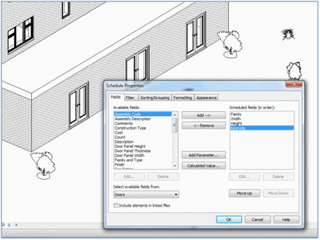
Figure 2 – Selecting the columns for your schedule
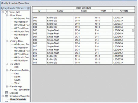
Figure 3 – A dynamic schedule that displays the values in the BIM
The big advantage of scheduling and taking off quantities using BIM software is that changes in the graphical view of the model are automatically reflected in the schedule, and changes in the schedule are automatically reflected in the graphical interface.
Building element properties
A NBS specification does not contain structured information about geometry, spatial relationships or quantities, but it does contain a huge amount of information about the properties of building elements. We are currently working on greatly improving the structure of this data to the point where NBS will be a Building Information Model in its own right. Each product in the specification will have a property set of marked up data, with typical options against each property. The relationship to guidance, technical standards and Building Regulations will be improved. Finally, the supporting information required for a contractor to install the product on site, for the designer to test that performance requirements upon completion and for the owner to maintain the building will be available.
Examples of use of the NBS BIM will include:
- An architect specifying a product by defining the required properties. The specification will be passed to the contractor who will be able to select from a list of available products that meet or exceed the requirements
- As the building elements have properties that can be interpreted by computer software, this will present exciting opportunities to do calculations, such as the quantity of embodied carbon or of recycled content. Opportunities such as the automatic calculation of BREEAM [5] points or automatic Building Regulation approval will become possible
- The comprehensive database of building element properties will also provide building owners and facility managers with improved accuracy and time savings when replacement products are required or when the building is refurbished, altered or eventually dismantled.
Use of data from different Building Information Models
It is unlikely that all of the information from a construction project can be contained in a single BIM. More typically there will be a number of BIMs that are stored in different proprietary format. For example, the architect’s CAD model could be in ArchiCAD format, the engineer’s CAD model in Revit and the specification information within NBS.
Linking models through a common reference
It is crucial that links can be made between the different BIMs and that information can be exported from one BIM and imported into another. Traditionally, in the UK, the relationship between the drawing, specification and bill of quantities has been the Common Arrangement of Work Sections (CAWS). This was first published in 1987 by CPIC [6], a committee representing major institutes across the UK construction industry (RIBA, RICS, CIBSE and ICE). CAWS allows a building component to be labelled by reference and title on drawings and in the specification and bill of quantities.
Recently at NBS, we have developed our software to allow other BIM software to reference a project specification and associate items in a CAD model with the specification clauses CAWS reference. So the designer can link an element in the CAD model such as a window with the clause in the NBS specification about the same window type.
Associating NBS specification clauses with the elements in the CAD model allows for improved efficiency savings and accuracy by helping to automate the process of annotation. Accuracy is improved further through the ability to report on the validity of the annotations prior to issuing the specification and drawings.
Figure 4 shows a screenshot from a prototype application with NBS Building and Graphisoft ArchiCAD interoperating. The CAD model has been annotated using NBS clause information. An annotation report has then been generated highlighting any corrections that are required prior to issue. This is a first step from NBS towards BIM integration between the CAD model and the specification.

Figure 4 – CAD and NBS working together
Importing and exporting information from BIMs
To go any further than the simple linking of two models through unique identifiers requires an agreed non-proprietary file format. Information can then be exported from one model to this file format and then imported into another model and round tripped. An example of this would be the architect designing the original building structure in Autodesk Revit, exporting this data into a non-proprietary file format and then the structural engineer then importing this into Bentley Microstation [7]. The structural engineer could make amends and then export the data for the Architect to receive to complete the “round trip”.
The two main non-proprietary file formats supported by most of the main CAD packages are Industry Foundation Classes (IFC) [8] and Green Building XML (gbXML) [9]. Figure 5 below shows the export options in Autodesk Revit to both gbXML and IFC format.
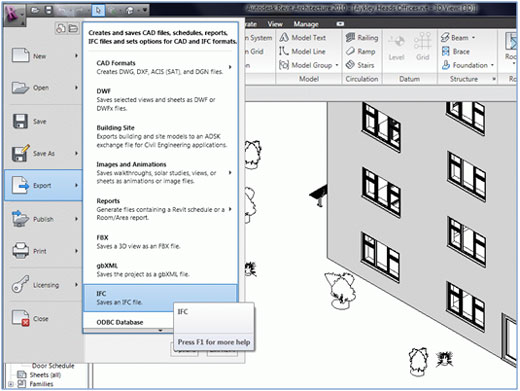
Figure 5 – Exporting the Revit BIM to IFC format
Having information in an industry open standard format allows all members of the project team, owners, operators, designers, constructors, regulators and other stakeholders to be able to work with BIM data from cradle to grave. It also allows software developers to produce applications that can work with data in a standard format to produce applications that analyse the energy consumption or structural performance of a building.
BuildingSMART are the international organisation that is responsible for IFC development. NBS are members of BuildingSMART, and we are actively looking into ways of importing IFC structured data into NBS and exporting NBS data into IFC format.
Conclusions
Building Information Modelling has come a long way in a relatively short time. It is being used by many in the construction industry to make efficiency savings and to improve the accuracy and coordination of documentation.
It is common for building information to be held in different models. Relationships must be built between the data to exploit the full benefit of BIM, and open standard formats must be used to translate data from one proprietary format to another.