With every new seminar, conference and article the construction industry comes closer to the 2016 date for the full implementation of 'Level 2' BIM in government projects. In this article Nunelah Design Consultants ![]() provide an interesting overview of the management processes they have instituted to support the legal responsibilities attendant with adopting BIM in projects they have been involved in.
provide an interesting overview of the management processes they have instituted to support the legal responsibilities attendant with adopting BIM in projects they have been involved in.
Introduction
As a multi-disciplinary practice Nunelah Design Consultants have worked with Building information modelling since 2005. The practice has since completed some 22 projects in the UK and five overseas using this process. The values of the projects have ranged from £700k to £55M with duration between 12-40 months.
Working effectively with BIM has necessitated various changes. Operationally there has been a change in the communication methods, technology requirements, resource and training. In the process of implementing processes to support BIM, the practice has also introduced new and more effective procedures into other business areas.
The legal issues around BIM
At the outset, most clients were oblivious to the value of BIM. This is also true for clients today, but to a lesser extent. In 2008 some of our institutional clients began to appreciate the value of modelling their projects and requiring information to be embedded into the model to facilitate full life cycle operations.
Traditionally, for a project, the geographical information was in one box, the design in another box and the operational information parked in further box. Integrating this information and providing the client with the ability to interrogate it, either for clarity or usefulness, has proved an immense cost saver for the client.
However, to provide this value added service with the mind-sets of traditional workflow and procedures raised important legal and practical issues, including:
- Who owned the information?
- Who was responsible for it and liable for the errors contained therein?
- How is the information collected and migrated?
- Who was getting paid for what?
- Who was controlling the project?
- In whose interest where the parties working?
- What nomenclatures and syntax should be used?
- How would the project be co-ordinated (the virtual aspect if it)?
- How would the project be procured with the modelled information?
- Could the contractor change the information? Is the contractor delivering the modelled information and the real asset?
- For international projects, terminology, jurisdiction, local workflows, intellectual property management were all important questions.
After a detailed consideration of these issues, the practice identified that there were no standards to dovetail to for guidance. To complicate matters, there were numerous building modelling applications and databases and none spoke a common language. Different disciplines had different allegiance to different technologies.
At the initial period the attempt was to use BIM with the traditional workflow and procedures; this was not particularly successful, and the practice soon realized that the overlay of traditional over the new workflow was unworkable. All the issues identified above had to be provided for through new processes.
Our approach to bridging the legal issues
Our objective was to ensure that there was clarity on the legal obligations for delivering a project. The legal obligations were contained in contracts which were typically built around traditional workflows; these were not discarded, but used as tools to formulate new processes to support the legal implications of working with BIM.
Client and the asset
The practice views the client as the absolute owner of the asset, both the real and the virtual model; the key difference with a regular project is that the deliverables are the built asset and the virtual model.
The start point for a project is the client's set of basic requirements. This should covey precisely the need or a vision and the client's view of the outcome – final product. The usual requirements is for the asset to be developed to be fit for purpose; developed in the most economical way and in the shortest possible time frame.
In implementing projects, the practice adopts a project roadmap. The roadmap sets the boundaries by the creation of project policy. The project policy framework includes the traditional items such as Client Responsibility, Legal Policy, Regulatory Compliance Policy, Procurement Policy and Risk Management Policy. Additional policies are added to specifically express collaboration. These are typically Collaboration Policy, Open book Policy, Technology & Information Policy, Delivery & Completion Policy and Facility Management Policy. The framework provides a proper foundation to build a project. It is best practice, especially in collaborative projects, to allow the client to approve the framework and appoint a project lead to drive the framework. This could be a Chief Executive or Lead Consultant depending on type of project and nature of the commitments of the parties. The duties of the lead are described contractually to cover the responsibility of driving the project.
An important aspect of the framework in terms of this discourse is the legal policy. Typically, the key outputs of the legal policy are:
A. Integrating the legal and commercial aspects of the project
B. Outlining the project's legal framework and relationships
C. Clear definitions
D. Identifying a hierarchy of legal obligations of all the parties involved
E. Determining multi-tier and cross framework contractual links.
F. Identify triggers of contractual rights and obligations and making them available to all.
BIM Projects
There are several schools of thought, whether a specific BIM document should be created or not. The nature of construction projects usually entails the generation of volumes of documents. The outputs from the legal policy become a specific section. Other sections may include the design requirements, the project plan, the schedule, the operational requirements and outputs from other project policies. It is our opinion that the creation of 'new' documentation termed BIM document is not necessary since the employer's requirement could be utilized to provide the necessary information. It may be argued that this is traditionally a provision of construction contracts. Traditionally yes, but in our approach the employer's requirement is brought forward in the project life cycle and becomes the focal point when the models are being created. The framework is the traditional Design & Build Contract, this we modify slightly to a Design & Virtual build and physical build Contract. The "contractor" becomes the "virtual asset contractor"; the rest of the professionals became the "virtual asset sub-contractors". Subtle but important rules are also introduced, for instance the client is not only the owner of the real, but also the absolute owner of the virtual product. The deliverable is modelled data not drawings in the traditional sense.
It is here the acronym BIM (building information modelling) enters the process in earnest. All other definitions aside, in our methodology the boundary of understanding is described as, "modelling the information for the building and not modelling the building for the information."
Relationships
Below is a typical project framework for a legal policy where BIM is adopted. This is based on a project valued at £10M. This is typical of a framework and is scalable for larger projects.
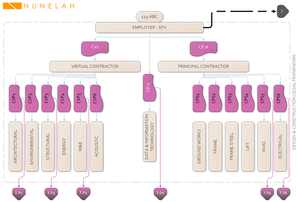
Exhibit 1 – Legal Framework
The framework is based on the existing Design & Build Contract form and clauses. All CV## are contract sections for the virtual delivery and CP## are contract sections for construction delivery. CD## is the contract section for technology and data management. All T.## links describe the contractual relationship required between collaborators and the delivery obligations, boundaries and more importantly the entry and exit points to the contractual obligations. Using this methodology, the framework is scalable e.g. multiple site, multiple contractors, multiply professionals etc. The key here is that this framework is visible to all collaborators, thus transparent.
The L1 is shown here as the contractual relation between the legal representation for the employer in providing clarity and stress testing this framework. For the purpose of this example, cross-disciplinary collaborations are not discussed here, but do exist in reality.
New role or function?
The BIM framework above highlights the requirement of a new role or function to manage the data being built into the model ensuring that it is available, current and accessible to the stakeholders in a collaborative environment. The role/function has been designated the 'BIM Manager'. For small projects the task could be undertaken by one of the professionals or the lead consultant. For larger projects, it is in our experience, best practice to assign this responsibility to a specific person unencumbered with other duties.
Our initial thoughts were that the new function would be an extension to the project manager's role and the task would be limited to procedure assembly, task monitoring, reporting and expediting in the conventional sense. In practice that the skill set includes IT knowledge and data management, construction knowledge and knowledge of building information modelling applications, data interfacing and software programming appreciation.
Model development
The start point for model development is the project meeting which is held before commencement of the project and at any time a new stakeholder enters the project. At this meeting the custodian of the model is identified usually the BIM Manager. Software tools and the data exchange methods are agreed, a list of interfacing requirements is also exchanged, system performance requirements and timelines for handling each part of the model are set out.
As in physical construction, it is fundamental to know who is responsible for what and how it is to be built. This brings to fore the issue of intellectual property. To ensure that the issue of intellectual property and with it responsibility/liability for information is clear, we devised a simple yet effective method of tracking and registering information provided from inception to completion. Like a real building the model is assembled from components, each component carries attributes which assign design responsibility, intellectual property rights and levels of indemnity. Whether components are created from scratch, or adopted or received from suppliers, they are tagged appropriately. The meeting is also used to allocate attributes to each component of the model. Attributes refer to IP - intellectual property, DR - Design responsibility and PI - Professional Indemnity.
Workflow
The workflow for the creation of the model should be modelled after the physical construction, it is best practice to create the virtual model the same way as the physical building. Virtual components, walls, floors, windows, lights, radiators, ducts, lifts, beams, columns are all created and included in the model. They are all theoretically tested and validated; before they are incorporated as part of the virtual construction. The creation of and the amendment of these elements is controlled by internal design reviews and gated methodology ensuring that no component is changed or altered after approval. When all the elements are ready, we simply catalogue these with a date and time stamp of design review. If an element has to be changed thereafter, this is done under our design change procedure. This work flow methodology is applied by all disciplines creating components.
Assignment, control and migration of model
IP (intellectual property) & DR (design responsibility) are assigned as attributes to components for a model set for a given project. As the elements within the model are created or adopted, all the information is added for that element. As different parties or persons create different elements within a model, the element is given the attribute of IP & DR. Each party or person is identified with a unique id. A parameter is used to set the IP and the DR attributes by inserting "IP=123/f": "DR=123/f": IP=a/123". There is no lock out mechanism to prevent someone changing this, but has to be controlled as part of the process. We control this is by the way of design reviews and automated data change capture.
The disciplines included are generally as described; however, when an element is adopted from a third party without change, then we also include their discipline in as well. We use a list that is universal, A=architect; B= Building surveyor; C=Civil; etc.
In the element verification design review, we ensure that IP and DR were assigned as they should have. We add a sub attribute to the IP and DR parameters. These are /d and /f where d = design and f = functional. Where an architect has created a form of unique structure and has value to the copyright, then this is classified a "d" attribute to the IP and DR. So if the building is not buildable or costs the earth, then we will know who to go to. We apply the "f" attribute when the functional properties are affected. This is the more important of the two. If the function is wrong, then the building could potentially have a flaw! These attributes are clear in definition and have worked for us so far and allows the practice manage responsibility and liability. To better explain the process, let's assume that a wall element is created with a required performance of say U value of 0.15 and a sound performance of 47dB and a thickness limit of 375mm, then there could be potentially three IP and DR attributes. One for the architect setting the dim requirements; the second for the energy engineers and the third for the acoustic engineers. All these would be tested and checked for in the design review. Only when the wall element achieves the performance requirement, is it allowed to migrate to the next stage.
The PI is assigned at the time of appointment of the design service. How this becomes relevant in the creation of the model, is disseminated by disciplines. The architectural elements carry architectural "a/PI" attribute. The architectural model is assembled using the architectural elements and the PI is covered within that discipline. When the model migrates to another discipline, say, structural the same philosophy applies, that all the elements added are stamped with an "s/PI" attribute and so on. Where an architectural component, say a wall is to be used as a structural element, then the wall carries a further PI attribute becoming "a/s/PI". Before the embedded structural content is returned, a design review is held. This review checks that the correct attributes IP, DR and PI have been applied. All the structural elements are catalogued in the same way as the architectural elements and the interfaces between the architectural model and structural elements identified. Where the inclusion of structural elements causes conflicts with the architectural model, all interfaces is evaluated, recorded and using the design change procedure amended as necessary. Depending on the type of structural construction for the building, the model is returned back to the structural camp to include rebar or connection details and the design review process is initiated again when model returns from the structural engineers.
At this design review, the PI is checked by an independent party. This party could be another company (for large projects >5M mainly) which are appointed at the outset. They usually have a role as project managers in the overall project. For smaller projects the discipline lead members are responsible for this activity. The check ensures that all elements are attributed correctly and where there is a doubt, the PI is distributed equally over the element in question. At the end of the design review the lead members of the disciplines sign a common agreement that the PI is appropriately assigned and accept their responsibility in the model. This agreement is retained in the project file. The same procedure applies with the other disciplines working on the model.
Depending on the size of the project, the value of the PI is set. This is usually 5-25M for any one discipline. Additional collateral warranties can be procured if necessary, but all are project specific.
The question of unauthorised edits rears its ugly head in each and every project. The elements are treated as standalone entities, and as described earlier, are frozen once the requirements are complete. You would then create the building using these elements. For example, if the designers require a variation to the element, e.g. a feature wall sweep for wall type EWS01, then they would request that a variant is produced. The variant goes through all the checks and is called EWS01.1. This means that the performance of other elements is unaffected, but the element is identified as being different. Analogy – blue panel or a red panel in a car. The IP, DR & PI is continually assigned.
Level of detail
The level of detail or the level of maturity that the model achieves is key in saving costs. The more the structured information that the contractor is provided with, the quicker the task is completed. Unlike the current stages of work, the philosophy we deployed was to ensure that the elements used for a project were predesigned and enriched at the outset, so the level of detail is intrinsic from the start.
In our process, the level of detail that the model reached before it was released to the contractor was the first part of the prescription and the level of detail that the model reached when it was handed to the client became second part of the prescription. Within our process we termed theses as P1 and P2 respectively for the virtual model. For ease of understanding, P1 would broadly include RIBA's F2 + G or AIA's LOD 400 and P2 would be As Built or AIA LOD 500.
These P1 and P2 triggers were inclusive to the contractual arrangements and listed in T.## links (described above) as deliverables for each discipline within the virtual and the real environments.
Drawings
Within our process, paper drawings are not deliverables. If paper documents are required, these were the responsibility of the individual stakeholders at their own cost. Within the modelling applications there are capabilities to create virtual drawings - Sheets. Within our processes, this would fall within the remit of the contractor. If the contractor does not have the expertise, appropriate stakeholders could be novated from the virtual camp. The production of these sheets is predominantly to facilitate construction.
Contractor and model
As with current specifications to the contractor, very little actually changes with the new process. All components and assemblies within the model are tagged with P – Prescriptive or D – Descriptive. Where descriptive, the contractor is allowed to select their preferred supplier and the model is updated by the contractor as part of their proposal. The level of information the contractor has to enter into the model or maintain the information already in the model is driven by the employer's requirement and the specifications.
Now with the advent of the NBS Create specifications and their plug-in to the modelling software, this would make the tracking and updating of the model specification and the model by the contractor more visible. The asset and the as built drawings, with the O&M, in the traditional workflow were simply replaced by the delivery of the built asset and the completed model as the as built information. The definition of the exact requirements is described in the P2 trigger.
Seamless?
Despite the advancement of modelling software tools in the last two years, interfacing between modelling applications remains an issue. Although feasible, it requires a considerable amount of time in ensuring that the virtual model and the data are transportable without the loss of fidelity.
From a legal perspective, the tests invoked within the triggers T.## as described above, require the parties, agreeing on an export or import protocol such as Buildsmarts IFC (Industry Foundation Class) and also agree on the level of fidelity at the outset. Using the same software tools is best practice and usually ensures efficiency and control.
Conclusion
While there are no specific test cases in our project history, we would like to highlight that there have been no disputes on BIM projects we have handled so far. This we see as evidence that our processes work. However, this is not the end of the journey and there are still challenges out there and more so now than ever before.
We think that the development and deployment of the BIM working method will benefit from the development of industry standards. Judging by the content of the standards being proposed, some work will be required ensure they provide the processes to support the legal obligations and responsibilities created when using the BIM working method.