The benefits gained from Building Information Modelling (BIM) correspond to the quality and depth of information in the model. Dr Stephen Hamil explains how BIM is not just 3D CAD and how master specification systems make a huge contribution to the 'I' in BIM.
A CAD example
When analyzing the benefits of Building Information Modelling it is often worth taking a step back and looking at a very simple example:
Consider an external wall (as illustrated in Figures 1 and 2). Within the latest CAD systems, walls are now three dimensional objects. The wall object is then broken down into the key products that make up its structure. For example, render, external brick leaf, cavity insulation, internal block leaf and plasterboard dry lining. Each of these is an object itself; this allows the creation of automatic schedules and quantity take-off. For example, within a click of a button, the number of bricks or the sheets of plasterboard within the building can be calculated.
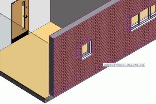
Figure 1 – An 'out of the box' wall in 3D CAD
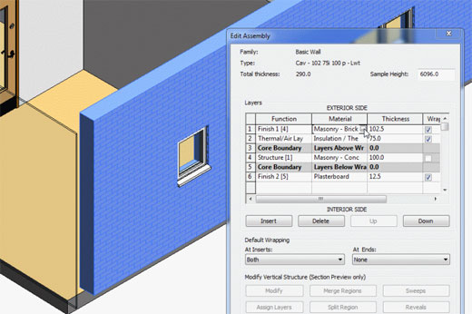
Figure 2 – Products that make up this wall's structure in 3D CAD
In addition to automatically generated quantities, 3D CAD models from different disciplines can be combined for clash detection. Users can add quite complex constraints so that the objects interact as expected. And, of course, spectacular visualisations can be created. However, can the full benefits of BIM be realised in these present 3D CAD models?
Consider the same external wall in a master specification system, for example, NBS Domestic Specification, our product for domestic new build, refurbishment and alteration work. Figure 3 displays the template description of the wall as a system in NBS Domestic Specification.
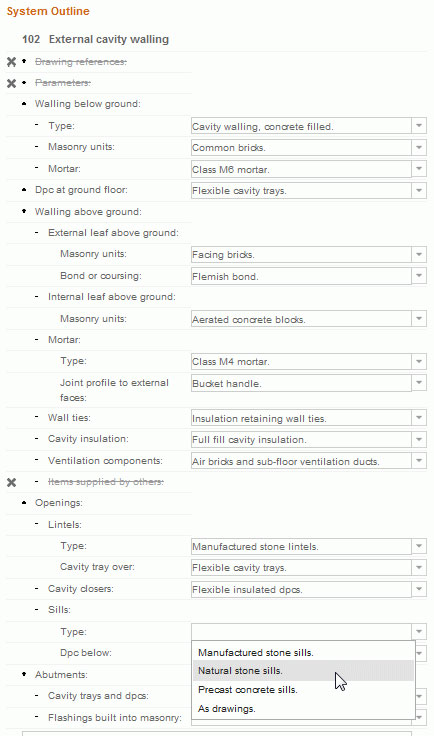
Figure 3 – External wall description in NBS Domestic Specification
Additional key products
Immediately, it is apparent that in addition to the key materials such as bricks, blocks and insulation, there are a number of other products that are not described as objects in the 3D CAD model. The external wall in NBS describes wall ties, cavity trays, weep holes, and lintels, and it's also evident that key products vary above and below the damp proof course.
Product definitions
Below this system description of the external wall, each of the products that make up the wall may be defined in greater detail, as for blocks in Figure 4.
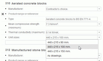
Figure 4 – Specification clause for one of the many products that make up the wall
In the vast majority of cases this detailed information would not be in your 3D CAD model. For example, what standard a particular product must comply to or what its compressive strength and thermal conductivity is.
The question arises: "Will this information one day be in CAD?"'. If so, the follow-up question is: "Who will maintain its currency?".
Workmanship
A true BIM must contain all of the information required to build and maintain the building. The expected standards for workmanship are a crucial part of this. Figure 5 displays a sample of the level of detail required to specify workmanship for our external wall.
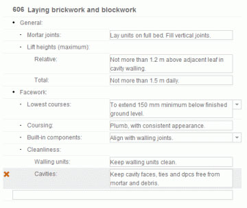
Figure 5 – Specification clause to ensure high quality workmanship
Performance requirements and their verification
The final component of a true BIM that this article considers is performance requirements - crucial in many designs. In modern procurement the designers quite often produce outline schemes and describe the included systems in terms of their performance requirements.
For instance, our external wall will not be specified in terms of the materials it is made from, but in terms of its structural, acoustic, thermal or aesthetic performance. However, listing performance requirements is only half of the picture, how these requirements are to be verified once the wall is complete is also essential. Master specification systems world-wide are increasingly providing and maintaining this content. This information must now be linked to the corresponding objects in 3D CAD systems.
Summary
It is clear that the use of 3D object-based CAD packages provide huge benefits over traditional 2D CAD. However, to really appreciate the true benefits of BIM, the information in 3D CAD models must be coordinated with information in master specification systems.
Figure 6 is an illustration from the very first edition of NBS in 1973. It shows the information on the drawing coordinated with the specification, quantities, standards, regulations and manufacturer information.
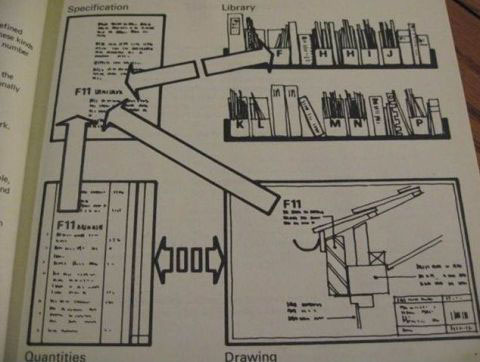
Figure 6 – Co-ordinated project information
Technology is now allowing us to accurately and more efficiently coordinate this information. This process has adopted the buzz word 'BIM'. The 3D CAD example that has been considered in this article is a simple wall, but multiply this across all of the systems and products that make up a building and its surrounding landscape and it is clear that integrating CAD and specification information is a vital step to truly adopting BIM.
When you say you have adopted BIM, pause for a moment. Ask yourself have you really adopted BIM or are you currently just using 3D CAD?