Last time we looked at Section 2: Information Requirements, this time we delve into the guidance relating to Section 3: Geometry Requirements.
This article is an abridged version of the guidance that accompanies the BIM object standard; NBS BIM Object Standard - Section 3: Geometry (Requires NBS ID).
See also: About the NBS BIM Object Standard
3.1 General
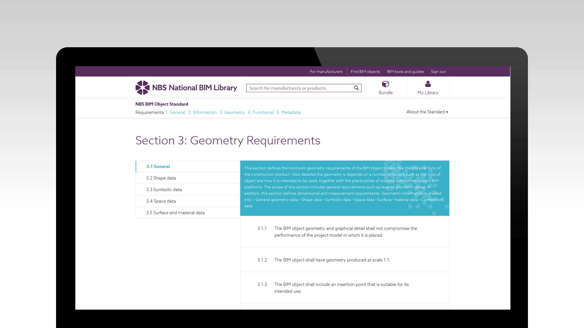
As a guiding principle, geometry and graphical detail contained in a BIM object should not compromise the performance of the project model in which it is placed. Elements of a construction product that will not be seen should not be modelled and where a manufacturer restricts certain criteria this information should, if appropriate, be built into the object where the BIM platform allows. For example, a door manufacturer's maximum unit size should be included.
Geometry should be produced at 1:1 scale using real world coordinates, as per the BIP 2207 Guide to BS 1192, to prevent any possible ambiguity.
The BIM object should include an insertion point (origin point) appropriate to its intended use. For example, a door or window would take a central insertion point allowing content to parametrically expand outwards.
Minimal use should be made of temporary info (like construction lines and reference material) and the object should contain parametric geometry (where supported by BIM platform and appropriate) which is locked to relevant reference elements such as planes, lines, levels and points. Dimensions and labels (where appropriate) should be constrained to reference planes. Dimensions should be derived automatically (using 'associative dimensioning' functions of the BIM platform) rather than text to ensure a direct relationship with geometry.
The BIM object's geometry should use millimeters (mm) as a unit of measure. The geometry should always have a defined purpose. Layered BIM objects should, where the BIM platform permits, represent the actual thickness of a layer (if not possible minimum thickness supported by BIM platform shall be used).
3.2 Shape data
A BIM object shall include a geometric representation (product shape / shape representation) of the space defined by a construction product's external boundry.
It shall include essential openings and geometric details allowing meaningful information to be gathered (For example, a door's essential openings would be seen as crucial. Modelling details such as mouldings are likely to add little in the way of structural value.
Where a construction product is not intended to be modifiable (perhaps it has a fixed form or is only available in one size and shape) then the BIM object should have fixed geometry to reflect the real world selection and availability of the product.
3.3 Symbolic data
The BIM object shall include a way of displaying a graphical convention at scales 1:20, 1:50 and 1:100 as per BS 8541-2. Level of detail and convention shall be appropriate to construction product and scale. BS 8541-2 conventions shall be a representation, a simplified representation or a symbol.
The BIM object may include information devices (a convention indicating an abstract item) or supplementary geometry to show abstract items and convey geometric information that would not otherwise be modelled (such as directional arrows and opening directions).
BS 1192-2 notes that geometric shapes for information devices are limited and therefore a number of meanings could be garnered. For this reason geometric shapes for information devices should not be used if its meaning is not determined by context and experience (a window opening direction or a flow direction arrow, for example).
Geometric features (such as depth of field and construction product parts) shall be distinguished using default lines, line types, hatching and fill patterns (as appropriate to the BIM platform). 2D lines can be used to convey relevant geometric details not otherwise modelled in 3D or to expand upon information (such as specific placement requirements - detailing requirements of a window when used in different wall constructions, for example).
This section defines the minimum geometry requirements of the BIM object to describe the physical form of the construction product. How detailed the geometry is depends on a number of factors such as the type of object and how it is intended to be used; together with the practicalities of working with contemporary BIM platforms.
3.4 Space data
A description of a product’s shape alone is not sufficient to check whether it is correctly installed. Products and equipment may require surrounding operation space or additional space requirements for transportation, installation and assembly. For this reason a BIM object can include 2D and 3D space data.
Such data might include:
| MInimum operation space |
That required for product to correctly function, including circulation and opening of doors, hatches, etc. |
| Access space |
That required for maintenance and operation of the construction product. Maintenance includes, but is not limited to, cleaning, servicing, repairing and replacing parts of the asset. |
| Placement and transportation space | That required for the largest single subassembly into which the product can be broken down to allow ingress to and egress from its place of installation in the built asset. |
| Installation space | That required for on-site assembly, installation or de-installation of the construction product. |
| Detection zone space | That required for motion detection, functional coverage and sensor/ detector range. |
3.5 Surface and material data
The BIM object may include colours, hatching, fill patterns or texture image files (to an appropriate scale) to reflect the construction product material and appearance in the relevant graphical view (Such as elevation, section, isometric and animation views).
Materials carry information regarding identity, performance and appearance. They can be used on their own, as finishes and coatings, as building products within an object, or to represent an option within an object. The level of information for a material to be qualified, quantified and specified within a project environment will vary from a simple name and description through to detailed technical information.
Materials may be assigned a specific colour or a designated render to control the outward appearance of the construction product or product surface. Simple representative colours help aid identification of the object within the model view (the model view appearance determines how the material looks as the designer is working within the BIM platform) and can be representative rather than the colour which reflects the actual product colour.
Renderings are photorealistic outputs from the BIM which show a more accurate depiction of the material than the model view. BIM platforms allow for the configuration of the rendered appearance of the materials, such as transparency and reflectivity.
Image files can also be used to represent the material’s appearance. Bitmaps and bump maps can give additional appearance of texture to image files. The image should be scaled correctly and allow for a repeated pattern.
The product surface is the coloured and textured outer boundary of the product’s shape; its rendered appearance responds to relative lighting and viewing angles.
The BIM object shall (as far as functionally possible within the BIM platform) allow for the individual control and selection of textures and colours for a material's constituent parts. Creating and assigning the material to the instance or type provides most flexibility for the designer.
Generic objects can either use representative colours for the construction product or white (where it it exists in a variety of colours).
Many BIM platforms include default materials via an in-built library and these can be used and included within a BIM object.
Previous: Exploring the NBS BIM Object Standard: Section 2 Information Requirements
Next: Exploring the NBS BIM Object Standard: Section 4: Functional Requirements
About the NBS BIM Object Standard
We introduced the NBS BIM Object Standard in part one of this series.
The NBS BIM Object Standard can be viewed online or downloaded as a .pdf document from www.nationalbimlibrary.com/nbs-bim-object-standard.
The online version includes comprehensive NBS guidance with background information, technical help and supporting content to help provide clarity and competency when creating BIM objects to the NBS BIM Object Standard.
Register for an NBS Account for free to access both the online version and to benefit from the additional NBS guidance.
BIM Object Standard Requirements are detailed in five sections (general requirements, information requirements, geometry requirements, functional requirements and metadata requirements). We'll be looking at these sections in more detail in subsequent parts of this series.
To keep up-to-date with the latest BIM guidance and standards why not sign up to the NBS eWeekly newsletter? Get the latest content from theNBS.com carefully crafted into a handy weekly email.
Sign up to the NBS eWeekly newsletter