

Note: this article is a summary of the presentation delivered by Patrick Crocock, Specification Lead at AHMM, as part of the RIBA Plan of Work 2020 webinar series.
The RIBA Plan of Work lists specifications as one of the critical information exchanges that are required on all construction projects. In particular:
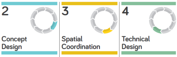
- An outline specification is required at the end of the ‘Concept Design’ stage.
- An updated outline specification is required at the end of the ‘Spatial Coordination’ stage.
- A final specification is required once all design tasks are completed at the end of the ‘Technical Design’ stage.
- Ultimately, any further specification amends during the construction stage must be captured in the final handover information.
In this article, the process followed at AHMM, which aligns to this RIBA Plan of Work framework, is outlined. Complexities that relate to the following are covered: preparing for specification writing; providing clarity between descriptive and prescriptive specifications; and coordinating specifications with the wider set of project information.
1. Preparation

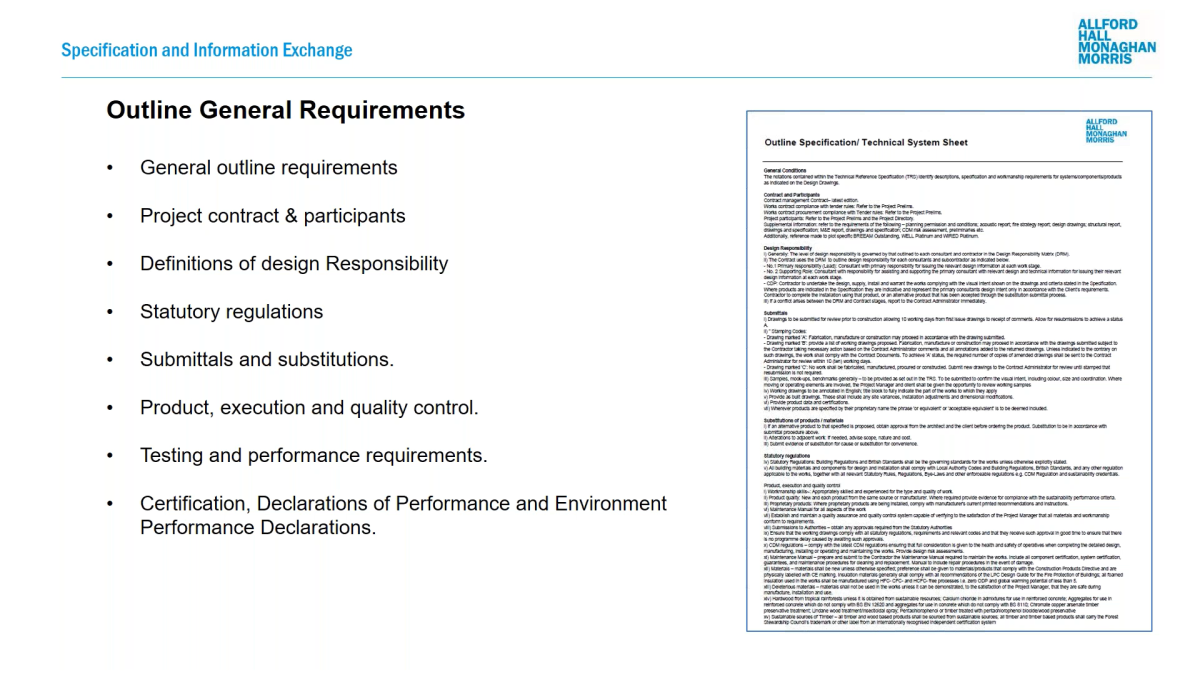
With respect to preparing for a project, documentation can be produced that is applicable to all projects. AHMM covers these requirements in a general requirements specification. Items such as: definitions; the employer’s design team and their contact details; standard requirements relating to statutory regulations; rules regarding submittals; and third-party certification are covered here. Figure 1.1 illustrates this high general requirements specification. Within NBS, the Prelims libraries are used to provide template clauses and associated guidance as a checklist of considerations.
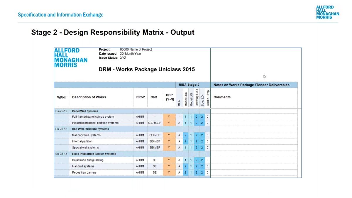
Another key preparation task is determining responsibilities in preparation for design work commencing. On typical projects, the required systems and products are not yet known. With this in mind, the second or third-level items in the Systems table of Uniclass 2015 are used to provide a pragmatic checklist. A free Excel toolbox is available to download on the RIBA website, and NBS also offers a ‘free-to-use’ online tool, the BIM Toolkit, to help project teams with this task. AHMM, however, uses a bespoke Excel version of this to allow for further data to be captured. Figure 1.2 below shows that primary and secondary responsibility is captured. Equally, the level of information required is defined as a combination of model detail, model information, drawing detail, specification information and also whether a standard data export is required. Notes against each high-level item are also captured – the LOD and LOI bandings from the BIM Toolkit are used.
Finally, office master technical specifications are authored and maintained for aspects of a job that can be similar across projects. AHMM maintains a library of office master specifications for key items such as partitions, floors, cladding, etc.
Patrick comments: ‘Preparation at the outset and the planning of your strategy always eases the burden of completing the specification during each work stage. It also eliminates risks of inconsistency and incomplete information’.
2. Design
As the architectural concept develops, the specific systems required begin to be agreed. Prior to the technical specification being created in NBS, AHMM develops a ‘technical systems sheet’ which list the different types of systems that will be required on the job.
By the end of the Concept Design stage, the aim is to have a completed sheet with each of the system types listed. Each of these systems will be classified by Uniclass 2015; each will also have a unique type code, a package code, an indication of whether this package will involve contractor design and associated notes. An example of this could be:
- Ss_25_12_60_60: ‘Panel cubicle system’.
- Type code = PCS-103.
- Description = For infant washrooms, low-level panels for adult supervision whilst maintaining privacy. To meet accessibility regulations.
- Package = 22.
- Contractor design = yes.
Figure 2.1 shows an illustration of this sheet containing a summary of the building systems. In combination with the general requirements specification and other sections (covering items such as whole building performance), this would form the ‘outline specification’ that is exchanged at the end of the Concept Design stage. Many of the requirements from the key project strategies (such as fire safety, sustainability, inclusive design, etc.) will have been developed in this outline specification.

This information is then further developed and coordinated with all of the disciplines as the Spatial Coordination stage continues. Ideally, each member of the design team will be taking the same approach to specification, and a coordinated set of information can be delivered as the outline specification is progressed.
The NBS specification is developed according to the technical systems sheet. Each specification will reflect the project requirements; it will use the agreed coding system, and the specification will be developed to meet the level of information need.
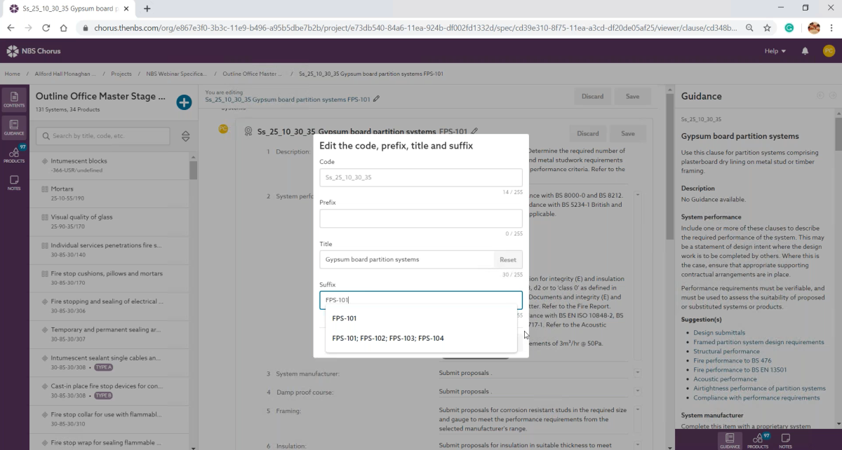
If a descriptive specification is required then the NBS system performance content will be used to define the contractor design portions of the job. If a prescriptive specification is required then the NBS specification will include the manufacturer products that form the system. There will, of course, be times when a descriptive specification will include a number of products that have been mandated by the client, or agreed with the planning authority. An example of this could be a roof-covering system that requires a specific clay roof tile to match the surroundings. Figure 2.2 shows a descriptive specification for a partition system that follows the AHMM coding scheme.
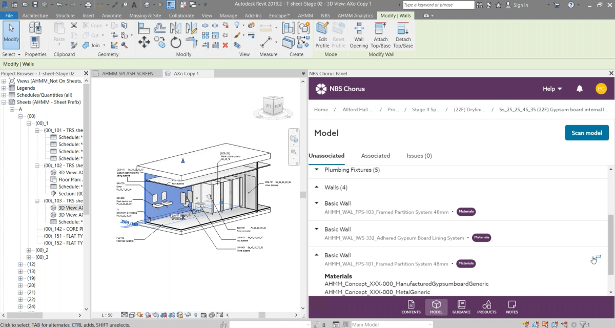
Coordinating the drawings and schedules with the specification is done by using the NBS Chorus plug-in for Autodesk Revit. Each type of system and product in Revit is associated with the equivalent specification clause in NBS. Figure 2.3 shows that the classification codes and type codes are used to annotate the objects in the model.
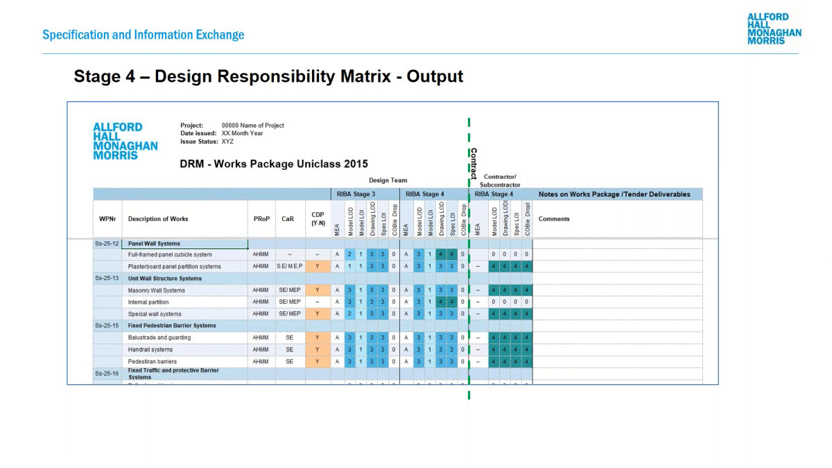
Throughout the design process, the design responsibility matrix has continued to develop. Of particular importance is the responsibility before and after the building contract has been awarded. Figure 2.4 below shows that, for the contractor design portions, the level of information within the specification stops at ‘banding 3’ – defined as a descriptive specification. Following the award of the building contract, the designer may be novated to work for the contractor’s team. In this situation, a further update to the design responsibility is required to determine whether each package will have its design finalized by specialist subcontractor or have the responsibilities and obligations for that package delegated to the novated designer.
Patrick commented: ‘Using NBS Chorus we have developed our building systems in line with design responsibility. We have descriptive specifications that define the contractor portions of work. We have fully prescriptive specifications that are fully designed by the consultant. Our Revit annotations have been generated through linking the model to the NBS specification. The Uniclass classifications, the prefixes and suffixes are on all drawings and schedules’.
3. Construction and handover

The RIBA Plan of Work makes it clear that the Technical Design and the ‘Manufacturing and Construction’ stages may overlap. This is increasingly likely on projects where there is a greater amount of contractor design. With this in mind, it is important to capture all specification decisions throughout stage 5 for when design, manufacturing and construction overlap. Equally, where substitutions are proposed and approved during the construction stage, these decisions should be recorded in revisions to the specification, updated by the party responsible for the final design.
The specification is the key document that defines the quality of the product, the quality of execution and the required work at completion. Therefore, throughout the construction phase, the work will be verified against the specification. Finally, a record of specification decisions should form part of the final handover information. Figure 3.1 illustrates some of these final tasks towards the end of any project.
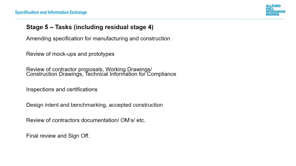
Patrick commented: ‘We review prototypes, we review contractor proposals and do inspections on site – these are reviewed against the specification. Finally we review the contractor’s documentation such as operation and maintenance manuals for handover’.